Wind Turbine Installation Boom Crane
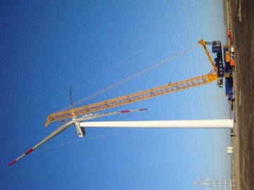
Our QLY2150 wind turbineinstallation boom crane adopts intelligent suspension tires which are fullyhydraulic and rotary. It also uses imported electro-hydraulic components, andthe lifter arm can realize straight, oblique and horizontal movement. Inaddition, the equipment can be conveniently transferred without having todismantle the arm and is applicable to only 5 meters wide dirt road. Dueto a maximum lifting height of 110m and maximum lifting capacity of 120t, thecrane is widely applicable to wind turbine installation with the power of 2.5MWor below.
The boom crane has an effective control system, which has the functions ofdisplay, commissioning, calibration, inspection, maintenance, etc. The displayis used to show the actual lifting weight, boom angle, working radius, liftingheight, speed, working hours, mileage, wind speed, engine temperature, fuelconsumption, cylinder temperature, and other parameters. Entering the password,the user has easy access to parameter setting. When a failure occurs, thedisplay can indicate relevant information and prompt operations or cut off thewindow for maintenance.
The crane control system makes use of imported RC controller and display,encoder and torque limiter, as well as closed-circuit surveillance unit. Ourlifting, slewing, luffing,servo, anti-backward, and auxiliary hydraulic systems adopts closed loop,featuring energy saving, high efficiency, good controllability, smooth start,stop and steering, non-impact, fast response operation, less heat, long servicelife. It also uses electro-hydraulic proportional control components tofacilitate accurate and intelligent control. While the electrical controlsystem uses CAN bus technology to for data transfer and improved reliability ofthe system.
The displays of the torque limiter, closed-circuit monitor and otherinstruments are all in the operator's direct field of vision. The torquelimiter display equipped in this boom crane is used for real-time detection ofcrane torque and other parameters, and the monitor display is used to show theoperating status, control parameter and alarm. There is an operating handle onthe left and right armrest, and the handle action can be switched by themonitor display button, with the separate action or allowable compound actiondisplayed in the form of text and graphics.
Our wind turbine installation boom crane is equipped with a variety of safetyprotection devices, such as the torque limiter, over-wind and over-dischargingprotection for the hook, mode switch, limit device and anti-overturn device forthe main boom, brake for the lifting mechanism, closed-circuit surveillancesystem, fault diagnosis system, black box, navigation light, anemometer,electronic level, lightning protection, boom tilt alarm, hook anti-loosingdevice, slewing and traveling alert, power limit load regulation and stallprotection, as well as monitoring instrument for the engine, etc.
Technical Specifications
| Working radius (m) | 8.4 | 10 | 12 | 14 | 16 | 18 | 20 | 22 | 24 | 26 | 28 | 30 | 32 | 34 | 36 | 38 |
| Lifting weight (t) | 120 | 120 | 120 | 120 | 120 | 119 | 107 | 97 | 89 | 82 | 75 | 70 | 64 | 58 | 50 | 40 |
| Boom length (m) | ≤ 82.0 | ≤ 96.0 | ||||||||||||||
2. Max. lifting capacity ofhoisting mechanism:120t
3. Safety factor of overturning stability: 1.5
4. The value in the table is calculated based on 200t counterweight.
5. The boom length can shorten 12.0m modulus.
6. The rated lifting weight includes hook and spreader weight.
Rated lifting height: 95m
Lifting speed: 0~
Luffing speed: 0~
Luffing max. elevationangle: 85°
Slewing speed: 0~
Working level: A3(lifting grade HC2)
Travelingconditions:
1. Empty speed (without counterweight): 0~
2. Adaptablelongitudinal slope: ±8%
3. Adaptablecross slope: ±3%
4. Suspensionself-leveling capability: ±300mm
5. Tire groundpressure: 0.45Mpa
6. Centerrotation radius of lower trolley: 16.5m
Hoistingconditions:
1. During thehoisting process, the X-type outrigger stretches out and stands on the ground.This action is controlled by the hydraulic system.
2. The spacing of four outriggers comes in square, 14m × 14m.
3. The allowable bearing force of each outrigger is 200t, with the groundpressure of 0.45Mpa.
4. All the tires are suspended and free from the force during this workingcondition.
Upper trolley
1. Axis number: 6
2. Number ofcolumns: 2
3. Suspensionnumber: 12
4. Number oftires: 48
5. Tire spec.:Engineering tire 1200R20, Φ1125
6. Max.
7. Outer rimdistance: 4.3m
8. Driving /driven wheel number: 24/24
9. Mass: 126t(including X-type outrigger)
10. Steering mode: Splay steering, transverse traveling
11. Installedcapacity: 440KW (share with uppertrolley, engine located in upper trolley)
12. Max.
13. Transport andhandling: block transport, quick connector (patent)
Upper trolley:
1. Rotary base
1.1 Base structure: Welded by Q345C plus imported NA-XTRA700 steel plate
1.2 Installed capacity: 440KW
1.3 Slewing ring:three-row roller slewing bearing, turning diameter 3150
1.4 Built-in equipment: Slewing, luffingand lifting hydraulic reducer, motor, winch, engine, hydraulic pump station,front-end suspension cab, back-end suspension counterweight
1.5 Mast structure: Flat steel frame structure welded by Q345C steel plate,with the upper end connected with pull rod and installed with moving pulley,while the bottom end connected with the front part of base structure.
1.6 Max. cell size and weightin long-distance transport: Slewing base L×H×W=15.12×2.74×3.18m, Weight: 33.1t
2. Back pull rod
It is composed of 2m, 4mshort section and 6m standard section, with a total length of 88.52m x 2. Each section is made of 42CrMo round bar,wrought into the flat head pin connected structure, and then quenched up to10.9 strength. The pin connected pullingplate is produced by 42CrMo flat bar, and heated to achieve up to 10.9-levelstrength. While the pin is manufactured from 42CrMo round steel, resulting in atotal weight of 6.5t.
3. Auxiliary bracing
It uses the standard lifting chain (GB/T20946-2007), with the model of
4. Boom
1.1 Arm type: Tube truss pin connected structure, cross-section four chordcenter size: 2.7 × 2.7m
1.2 Chord material: German imported high-strength welded steel pipe, Φ219.1 ×20 and Φ219.1 × 16 two models, yield strength = 690Mpa. Ear plate:
1.3 Ventral pole material: Q345Φ140 × 8 steel pipe
1.4 Welding materials and processes: Provided by German
1.5 Interchangeability of truss connection: 100%
1.6 Anti-overturnfuel tank: Diameter: Φ250, Stroke: 2500
1.7 Max. transport cell sizeand weight: L×H×W=12.32×3.02×3.02m, Weight: 9.9t
Traveling mechanism:
1. Two axes x twocolumns = 16 wheels (same parameters as lower trolley)
2. Total height:4m, universal joint bearing on the top surface, bearing capacity: 70 tons,weight: 16 tons, ground pressure 0.45Mpa
3. It has no driving force, but is available with the manual steeringmechanism.
Hoisting and the luffingrope standards:
1. Hoisting rope: German Pfeifer non-rotating wire rope Φ28
2.
Paint standards:
1. All metal structure surfaces shall go through shot blasting or mechanicalmanual rust removing process, so as to reach the Sa2 or St2.5 grade ofGB/8923-88.
2. All the structures shall be painted with two undercoats, an intermediatecoat and two finishes, with the total dry film thickness not less than 125um.


")


